


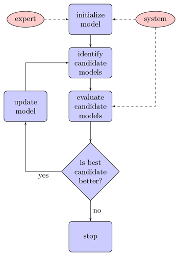
With PGF/TikZ you can draw flow charts with relative ease. This flow chart from [1] outlines an algorithm for identifying the parameters of an autonomous underwater vehicle model.
Note that relative node placement has been used to avoid placing nodes explicitly. This feature was introduced in PGF/TikZ >= 1.09.
| [1] | Bossley, K.; Brown, M. & Harris, C. Neurofuzzy identification of an autonomous underwater vehicle International Journal of Systems Science, 1999, 30, 901-913 |
Edit and compile if you like:
\documentclass{article}

\usepackage[latin1]{inputenc}
\usepackage{tikz}
\usetikzlibrary{shapes,arrows}

\usepackage[active,tightpage]{preview}
\PreviewEnvironment{tikzpicture}
\setlength\PreviewBorder{5pt}%


\begin{document}
\pagestyle{empty}


% Define block styles
\tikzstyle{decision} = [diamond, draw, fill=blue!20,
    text width=4.5em, text badly centered, node distance=3cm, inner sep=0pt]
\tikzstyle{block} = [rectangle, draw, fill=blue!20,
    text width=5em, text centered, rounded corners, minimum height=4em]
\tikzstyle{line} = [draw, -latex']
\tikzstyle{cloud} = [draw, ellipse,fill=red!20, node distance=3cm,
    minimum height=2em]

\begin{tikzpicture}[node distance = 2cm, auto]
    % Place nodes
    \node [block] (init) {initialize model};
    \node [cloud, left of=init] (expert) {expert};
    \node [cloud, right of=init] (system) {system};
    \node [block, below of=init] (identify) {identify candidate models};
    \node [block, below of=identify] (evaluate) {evaluate candidate models};
    \node [block, left of=evaluate, node distance=3cm] (update) {update model};
    \node [decision, below of=evaluate] (decide) {is best candidate better?};
    \node [block, below of=decide, node distance=3cm] (stop) {stop};
    % Draw edges
    \path [line] (init) -- (identify);
    \path [line] (identify) -- (evaluate);
    \path [line] (evaluate) -- (decide);
    \path [line] (decide) -| node [near start] {yes} (update);
    \path [line] (update) |- (identify);
    \path [line] (decide) -- node {no}(stop);
    \path [line,dashed] (expert) -- (init);
    \path [line,dashed] (system) -- (init);
    \path [line,dashed] (system) |- (evaluate);
\end{tikzpicture}


\end{document}
Click to download: simple-flow-chart.tex • simple-flow-chart.pdf
Open in Overleaf: simple-flow-chart.tex