


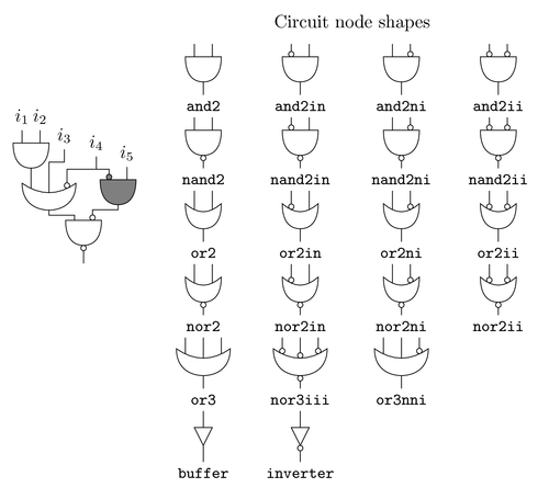
The circuits library, written by Juergen Werber and Cristoph Bartoschek, is a library of custom node shapes for drawing logic circuits. The library code is well written and easy to follow. Adding new variants of the shapes is straightforward.
To run the example the pgflibrarytikzcircuits.code.tex file is needed:
Note that the library is loaded using:
\usetikzlibrary{circuits}
Edit and compile if you like:
% Logic circuits library
% Authors: Juergen Werber and Christoph Bartoschek
\documentclass{article}

\usepackage{tikz}
% load circuits library
\usetikzlibrary{circuits}


\begin{document}


\begin{tikzpicture}[scale=0.5,cktbaselength=0.5pt]
\draw (6,0) node[nand2ni,anchor=tip,draw] (n4) {}
      (n4.z) -- +(0mm,-5mm)
      (n4.b) |- ++(10mm,2mm) -- ++(0mm,2mm)
      node[and2in,anchor=z,draw,fill=gray] (n3) {}
      (n4.a) |- ++(-10mm,2mm) -- ++(0mm,2mm)
      node[or3nni,anchor=tip,draw] (n2) {}
      (n3.b) -- +(0mm,5mm) node[above] {$i_5$}
      (n3.a) |- ++(-5mm,2mm)
      coordinate (p) -- +(0mm,5mm) node[above] {$i_4$}
      (n2.c) |- (p)
      (n2.b) |- ++(6mm,12mm) -- +(0mm,5mm) node[above] {$i_3$}
      (n2.a) -- +(0mm,8mm)
      node[and2,anchor=tip,draw] (n1) {}
      (n1.b) -- +(0mm,5mm) node[above] {$i_2$}
      (n1.a) -- +(0mm,5mm) node[above] {$i_1$};
\end{tikzpicture}
%
% Define a few helper macros to save typing
% The \spacer macro inserts a dummy node and defines the t (top) and
% b (bottom) coordinates. t and b are used to align the pins
\newcommand\spacer{%
\node[anchor=south,minimum height=1cm,inner sep=0pt, outer sep=0pt] (tmp) {};%
\path (tmp.north) coordinate (t) (tmp.south) coordinate (b);%
}
% Draw connecting pins. Note the use of the t and b coordinates defined
% in the \spacer macro
\newcommand\drawpins[1]{%
\draw (#1.a) -- (t -| #1.a)
      (#1.b) -- (t -| #1.b)
      (#1.z) -- (b -| #1.z);
}
% Draw pins for a logic gate with tree inputs
\newcommand\drawpinsiii[1]{%
\draw (#1.a) -- (t -| #1.a)
      (#1.b) -- (t -| #1.b)
      (#1.c) -- (t -| #1.c)
      (#1.z) -- (b -| #1.z);
}
%
\begin{tikzpicture}[scale=0.5,cktbaselength=0.5pt,baseline]
\tikzstyle{gate} = [draw,anchor=center,yshift=5mm]
\tikzstyle{ann} = [below,font=\small\tt]
\matrix[column sep=0.5cm] (circuit shapes) {
    % Use the first column to place a dummy spacer node
    \spacer &[-0.5cm] % remove column spacing
    \node[and2,gate] (N10) {} node[ann] {and2};\drawpins{N10} &
    \node[and2in,gate] (N20) {} node[ann] {and2in};\drawpins{N20} &
    \node[and2ni,gate] (N30) {} node[ann] {and2ni};\drawpins{N30} &
    \node[and2ii,gate] (N40) {} node[ann] {and2ii};\drawpins{N40} \\
    \spacer &
    \node[nand2,gate] (N11) {} node[ann] {nand2};\drawpins{N11} &
    \node[nand2in,gate] (N21) {} node[ann] {nand2in};\drawpins{N21} &
    \node[nand2ni,gate] (N31) {} node[ann] {nand2ni};\drawpins{N31} &
    \node[nand2ii,gate] (N41) {} node[ann] {nand2ii};\drawpins{N41} \\
    \spacer &
    \node[or2,gate] (N12) {} node[ann] {or2};\drawpins{N12} &
    \node[or2in,gate] (N22) {} node[ann] {or2in};\drawpins{N22} &
    \node[or2ni,gate] (N32) {} node[ann] {or2ni};\drawpins{N32} &
    \node[or2ii,gate] (N42) {} node[ann] {or2ii};\drawpins{N42} \\
    \spacer &
    \node[nor2,gate] (N13) {} node[ann] {nor2};\drawpins{N13} &
    \node[nor2in,gate] (N23) {} node[ann] {nor2in};\drawpins{N23} &
    \node[nor2ni,gate] (N33) {} node[ann] {nor2ni};\drawpins{N33} &
    \node[nor2ii,gate] (N43) {} node[ann] {nor2ii};\drawpins{N43} \\
    \spacer &
    \node[or3,gate] (N14) {} node[ann] {or3};\drawpinsiii{N14} &
    \node[nor3iii,gate] (N24) {} node[ann] {nor3iii};\drawpinsiii{N24} &
    \node[or3nni,gate] (N34) {} node[ann] {or3nni};\drawpinsiii{N34} \\
    \spacer &
    \node[buffer,gate] (buf) {} node[ann] {buffer};
    \draw (buf.z) -- (buf.z |- b)
          (buf.a) -- (buf.a |- t); &
    \node[inverter,gate] (inv) {} node[ann] {inverter};
    \draw (inv.z) -- (inv.z |- b)
          (inv.a) -- (inv.a |- t); \\
};%
\node[above] at (circuit shapes.north) {Circuit node shapes};%
\end{tikzpicture}%


\end{document}
Click to download: logic-circuits-library.tex • logic-circuits-library.pdf
Open in Overleaf: logic-circuits-library.tex