


CircuiTikZ is a set of LaTeX macros designed to make it easy to draw electrical networks in scientific publications. It provides a convenient syntax based on to-paths to place the various components. The examples below are from the CircuiTikZ examples page.
Edit and compile if you like:
\documentclass{article}
\usepackage[symbols]{circuitikz}
\usepackage{tikz}
\begin{document}
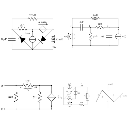
\begin{circuitikz} \draw
(0,0) to[C, l=$10\micro\farad$] (0,2) -- (0,3)
to[R, l=$2.2\kilo\ohm$] (4,3) -- (4,2)
to[L, l=$12\milli\henry$, i=$i_1$] (4,0) -- (0,0)
(4,2) to[D*, *-*] (2,0) to [D*, -*] (0,2)
to[R, l=$1\kilo\ohm$] (2,2) to[cV, v=$0.3\kilo\ohm i_1$] (4,2)
(2,0) to[I, i=$1\milli\ampere$:15, -*] (2,2)
;
\end{circuitikz}
\begin{circuitikz} \draw
(0,0) node[ground] {}
to[V, v=$e(t)$, *-*] (0,2) to[C, l=$4\nano\farad$] (2,2)
to [R, l=$\frac{1}{4}\kilo\ohm$, *-*] (2,0)
(2,2) to[R, l=$1\kilo\ohm$] (4,2)
to[C, l=$2\nano\farad$:-90, *-*] (4,0)
(5,0) to[I, i=$a(t)$:-90, -*] (5,2) -- (4,2)
(0,0) -- (5,0)
(0,2) -- (0,3) to[L, l=$2\milli\henry$] (5,3) -- (5,2)
{[anchor=south east] (0,2) node {1} (2,2) node {2} (4,2) node {3}}
;\end{circuitikz}
\begin{circuitikz} \draw
(0,0) node[anchor=east]{B}
to[short, o-*] (1,0)
to[R, l=$20\ohm$, *-*] (1,2)
to [R, v=$v_x$, l=$10\ohm$] (3,2)
to[short] (4,2) to[cI, i=$\frac{\siemens}{5}v_x$, *-*] (4,0)
to[short] (3,0) to[R, l=$5\ohm$, *-*] (3,2)
(3,0) -- (1,0)
(1,2) to[short, *-o] (0,2)
node[anchor=east]{A}
;\end{circuitikz}
\begin{circuitikz} \draw
(0,2) to[I, i=$1\milli\ampere$] (2,2)
to [R, l=$2\kilo\ohm$:-90, *-*] (0,0)
to [R, l=$2\kilo\ohm$] (2,0)
to[V, v=$2\volt$:-90] (2,2)
to[cspst, l=$t_0$] (4,2) -- (4,1.5)
to [generic, l=1, i=$i_1$, v=$v_1$] (4,-.5) -- (4,-1)
(0,2) -- (0,-1) to[V, v=$4\volt$] (2,-1)
to [R, l=$1\kilo\ohm$] (4,-1);
\begin{scope}[xshift=7.5cm, yshift=.5cm]
\draw [->] (-2,0)--(2.5,0) node[anchor=west] {$v_1 [\volt]$};
\draw [->] (0,-2)--(0,2) node[anchor=west] {$i_1 [\milli\ampere]$} ;
\draw (-1,0) node[anchor=north] {-2} (1,0) node[anchor=south] {2}
(0,1) node[anchor=west] {4} (0,-1) node[anchor=east] {-4} (2,0)
node[anchor=north west] {4} (-1.5,0) node[anchor=south east] {-3};
\draw [thick]
(-2,-1) -- (-1,1) -- (1,-1) -- (2,0) -- (2.5,.5);
\draw [dotted]
(-1,1) -- (-1,0) (1,-1) -- (1,0) (-1,1) -- (0,1) (1,-1) -- (0,-1);
\end{scope}
\end{circuitikz}
\end{document} Click to download: circuitikz.tex • circuitikz.pdf
Open in Overleaf: circuitikz.tex
edit: Link updated.
Comments
#1 Mary, July 5, 2009 at 7:36 p.m.
Hi! Congratulations and thanks to the author by the package.
How do I get the motors in the circuit? I have not found this symbol
thank you very much
#2 Kjell Magne Fauske, July 5, 2009 at 8:17 p.m.
Mary, you should ask Massimo Readelli about this. I’m sure that he can help.
#4 Vesa Linja-aho, October 3, 2010 at 12:50 a.m.
Hi,
I had some problems with this example. First, I got an error message:
! LaTeX Error: Unknown option symbols’ for packagecircuitikz’.
Then I looked at the documentation: http://mirror.ctan.org/graphics/pgf/contrib/circuitikz/doc/latex/circuitikz/circuitikzmanual.pdf
And noticed that “symbols”-option is obsolete. I removed it, but then I started having problems with those \micro\farad -stuff.
How to fix:
\usepackage[symbols]{circuitikz} changed to \usepackage[siunitx]{circuitikz}
Add \SI{}{}, for every component. Like this:
WRONG: [C, l=$10\micro\farad$]
FIXED: [C, l=$\SI{10}{\micro\farad}$]
#5 Vesa Linja-aho, October 3, 2010 at 1:08 a.m.
Just figured out a simpler way: just edit the beginning of the file to:
\documentclass{article}
\usepackage[free-standing-units]{siunitx}
\usepackage{circuitikz}
\usepackage{tikz}´
\begin{document}
#6 François, January 1, 2012 at 1:59 p.m.
And I would add that now (2012) the “free-standing-units” option is also obsolete.
Now it works fine with this preamble:
\documentclass{article}
\usepackage{tikz} \usepackage{circuitikz} \usepackage{siunitx}
\begin{document}
#7 Tiffany Hayes, February 10, 2012 at 11:40 p.m.
So you still need to use the \SI command I noticed. Also, I keep getting units under other circuit parts (but no errors from LaTex). Is there any way to just move the labels, or do I just need to enlarge the size of my circuit? I’m using the code as above, but with the \SI inserted as described above.
#8 Dave, March 7, 2012 at 8:27 p.m.
Hey, is there a way to create a caption above a resistor and the related value below the resitor?
#9 Anon, April 18, 2012 at 9:20 p.m.
I don’t see how to download the CircuiTikz files – the links are 404 not found and it looks as though Massimo Redaelli does not exist at the faculty list of the Dipartimento di Elettronica e Informazione (DEI) website. Could someone who has the packages let me know?
#10 Jannik, May 11, 2012 at 7:25 p.m.
Try https://ctan.org/pkg/circuitikz or your Tex Live Manager
#11 Jeff Hein, May 31, 2012 at 2:51 a.m.
This is simply amazing! Thank you so much for your hard work!
#12 Alex Mason, July 10, 2012 at 11:56 a.m.
Hi all
I have a slightly related issue with this to do with nodes.
In the documentation it says to use things like o_o or _ to produce nodes on the ends of components. However LaTeX gives the error that it does not know the keys o_o or _.
Perhaps they have been replaced or removed. Does anyone know?
#13 fred, September 14, 2012 at 6:30 p.m.
Does anybody know if there is a circuit symbol for varistors,MOVs, or surge arrestors? Thanks
#14 Charlie, October 17, 2012 at 8:41 p.m.
The links to the Circuitikz homepage are broken.
#15 Tony, June 26, 2013 at 3:16 a.m.
The hollow circles at the end of a line is produced w/ -o (right), or o- (left), per the manual samples.
Mr. Redaelli’s circuitikz manual provides this URL for source, and also has useful examples, symbol list